Build guide
Assemble the robot
About 45 minutes of reading and 110 minutes of building (tutorial v1.0, 27 Sep 2025). Figures are from that tutorial. Geometry and encoder ratios are from Rezeck et al., Auton. Robot (2023).
Casters · Motors · Wheels · Battery · Encoders · Board · E-hat · Troubleshooting
Casters
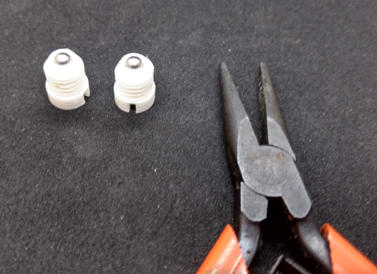
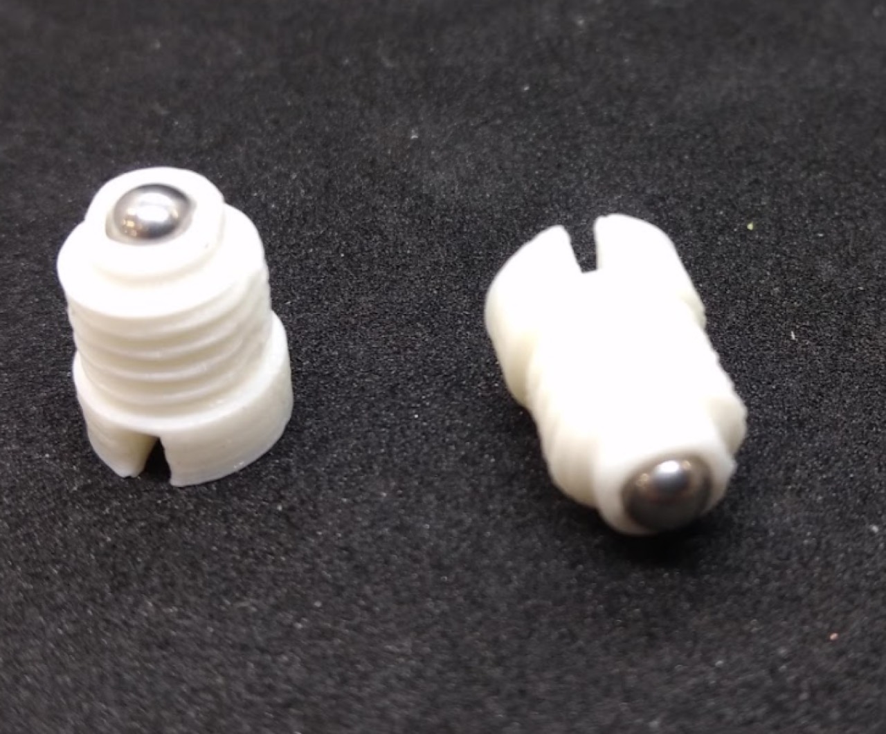
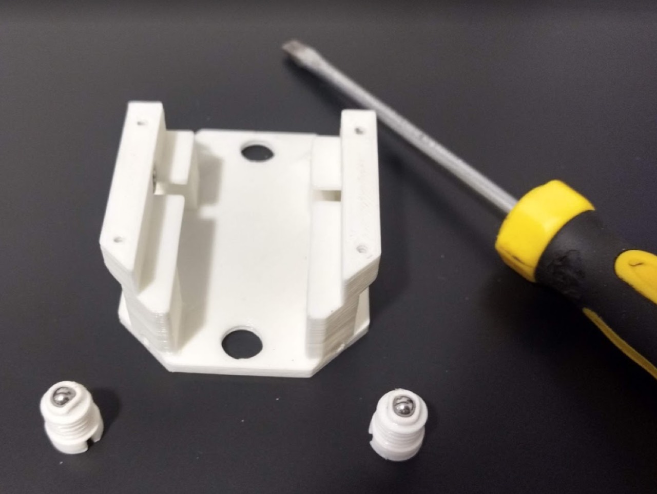
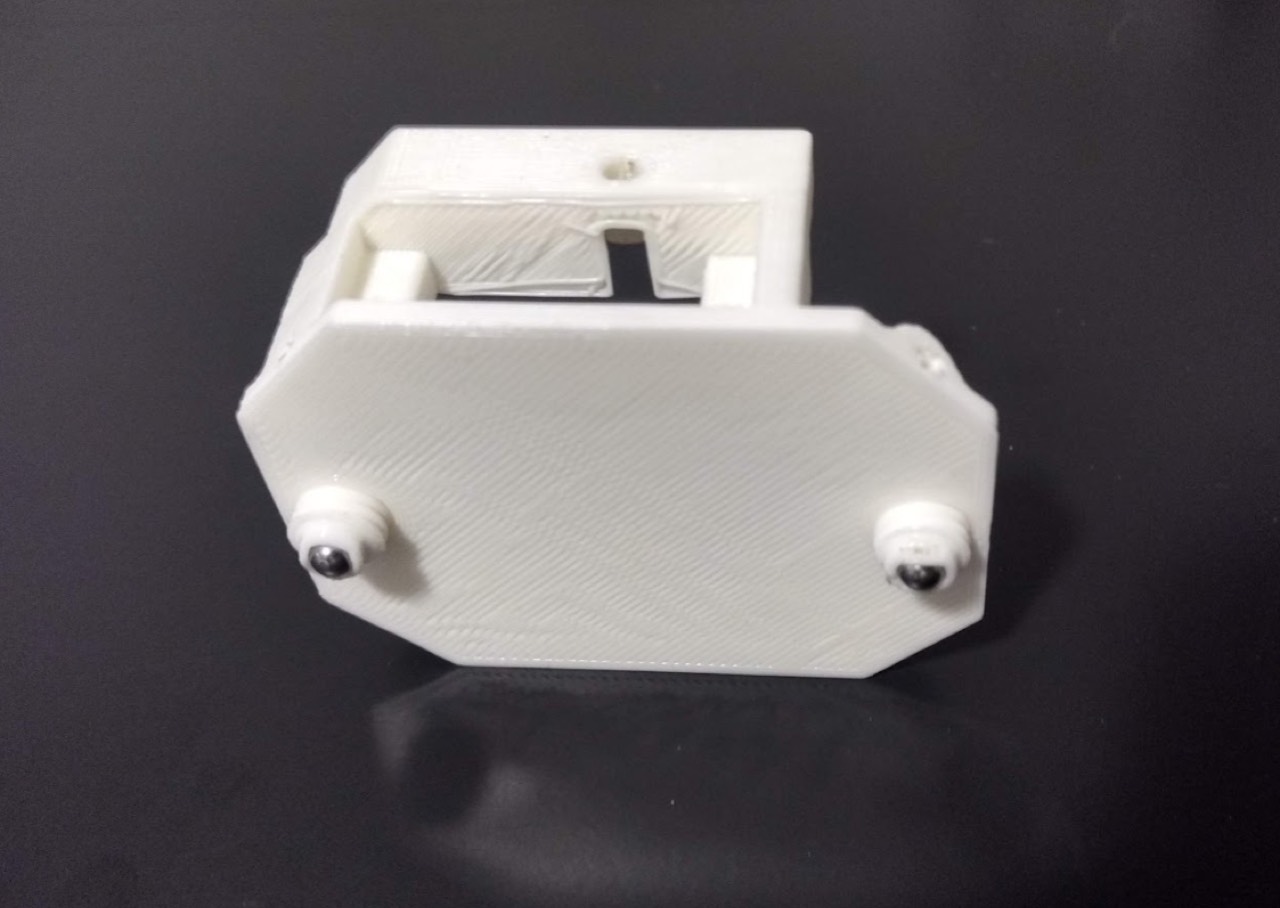
Take a printed caster shell, drop in a 4 mm steel ball, and crimp the rim with pliers so the ball stays in but still turns. Screw both casters to Chassis A. Set the height so the chassis sits level.
Motors
Prefer SG90 units already converted to continuous rotation. The tutorial recommends the green-label variant (no resistor swap). Stock angular servos need a CR modification first; after that, command ~1500 µs to center.
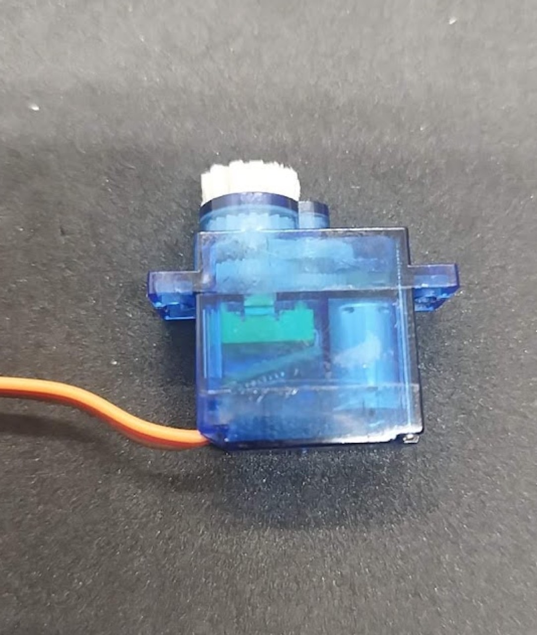
Gear adapter
- Pick a stock horn that fits the printed motor gear. Cut it down to the cylindrical hub. Wear glasses — chips fly.
- Trim the hub until it press-fits the gear. A small drop of cyanoacrylate at the interface; keep glue off the teeth.
- If the servo shaft sticks out, shorten it ~1.00–1.20 mm, cut flat.
- Fasten with the original horn screw. Do not overtighten — friction kills the mesh.
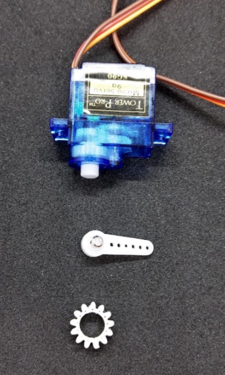
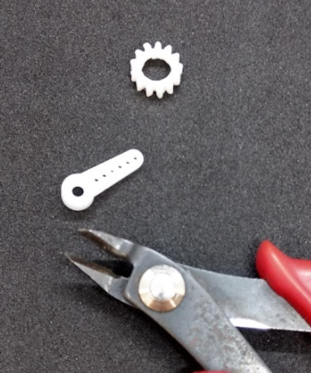
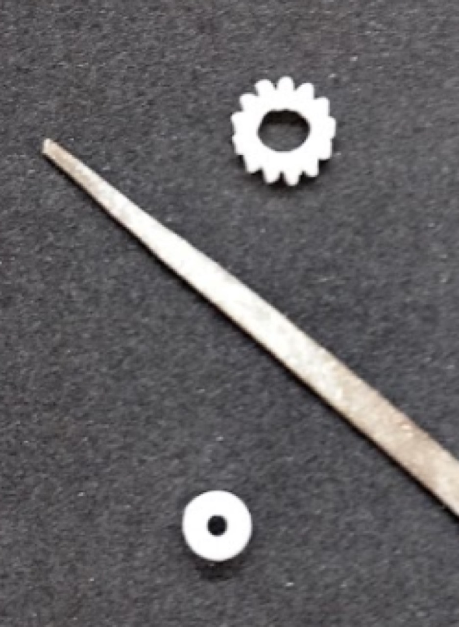
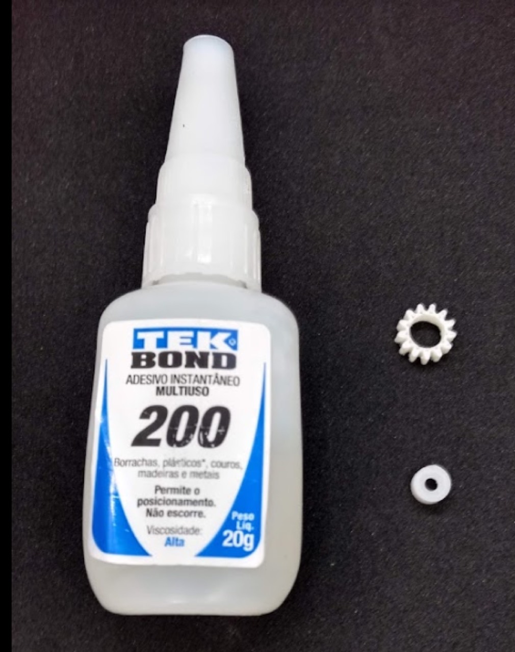
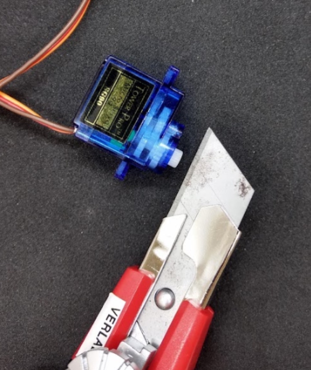
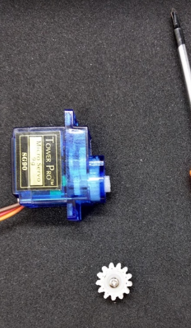
Mount each servo on Chassis A. Align both outputs at the stop pulse (1500 µs). Leave the mount screws slightly loose so the 1:1 gear train can sit. Trim motor cables to about 10 cm.
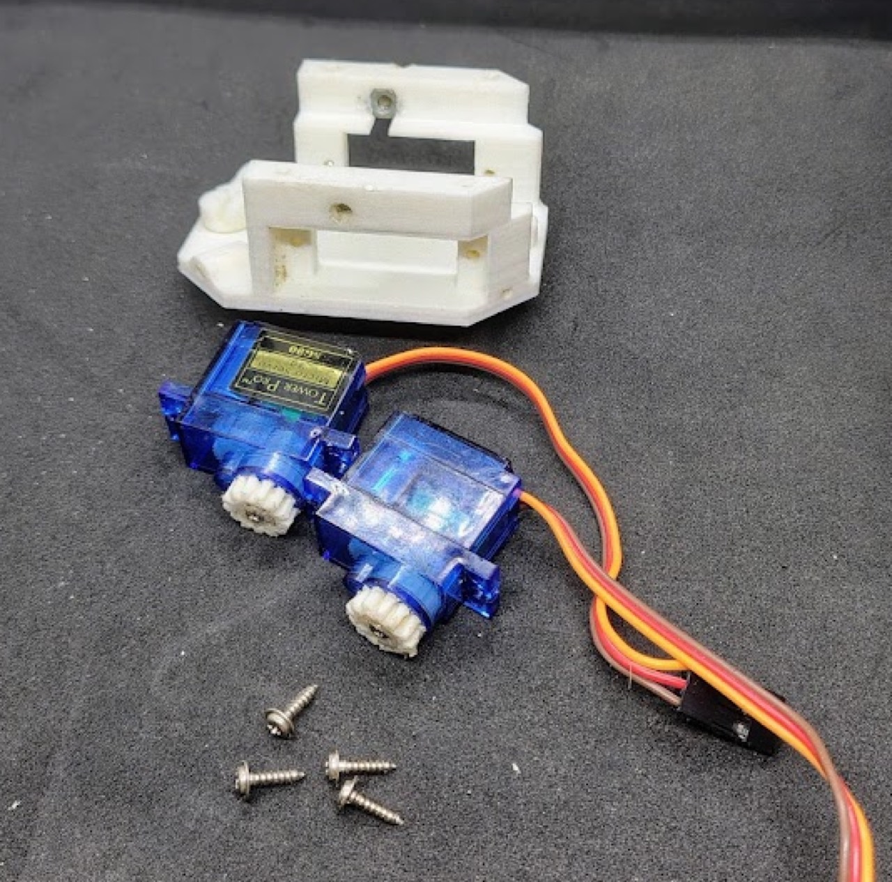
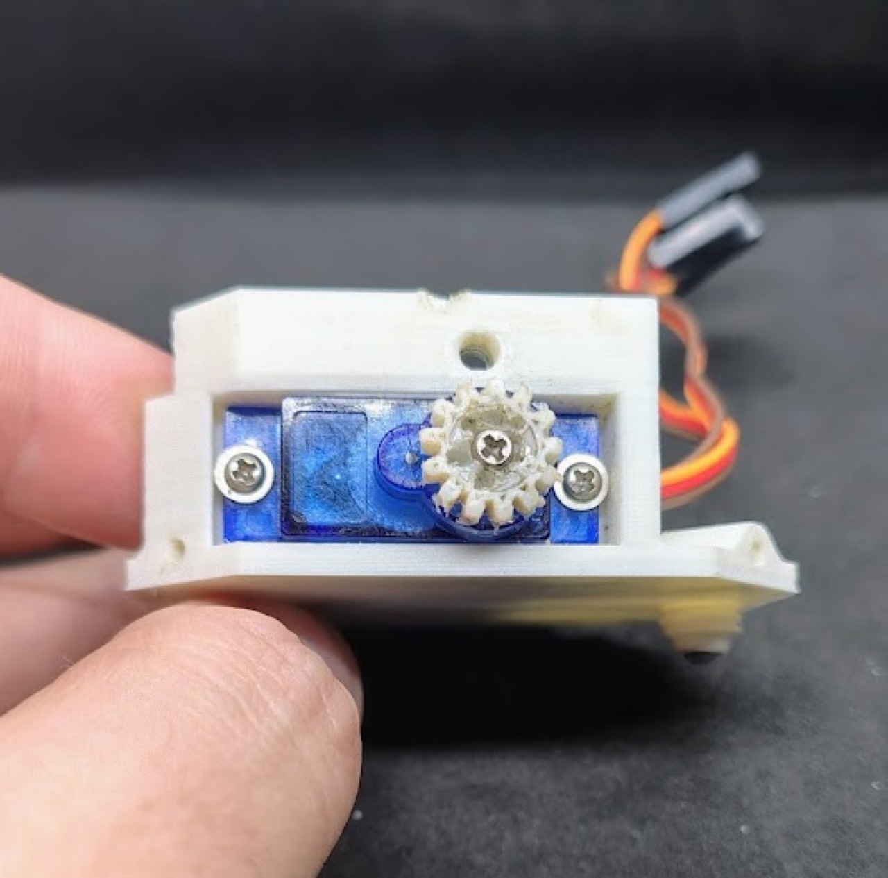
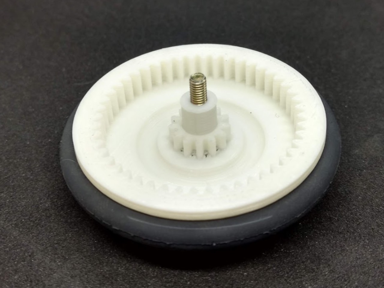
The paper’s drivetrain is a 1:1 motor–wheel gear plus a 1:6 wheel–encoder gear. Combined with the 48 PPR mouse encoder that is a 1.25° / 0.54 mm wheel step.
Wheels
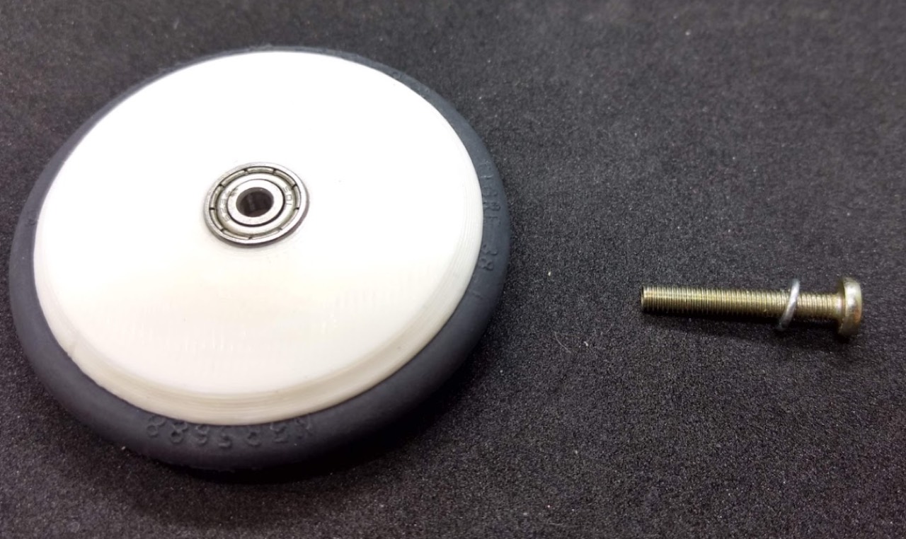
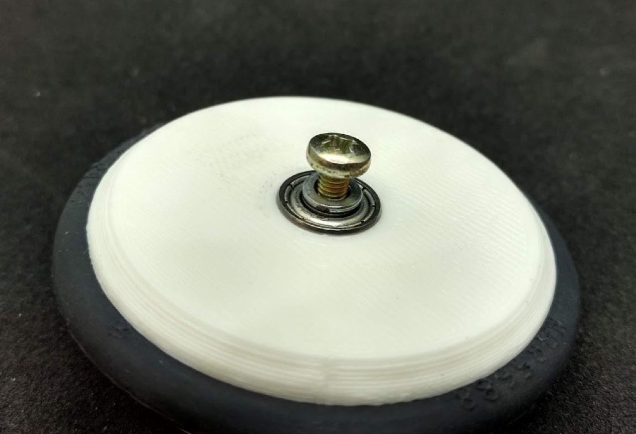
Press a 623ZZ into each printed hub (vise or a flat spacer — do not hammer the bearing). Seat the O-ring. Fit the printed shaft sleeve so the wheel turns with almost no backlash and no wobble.
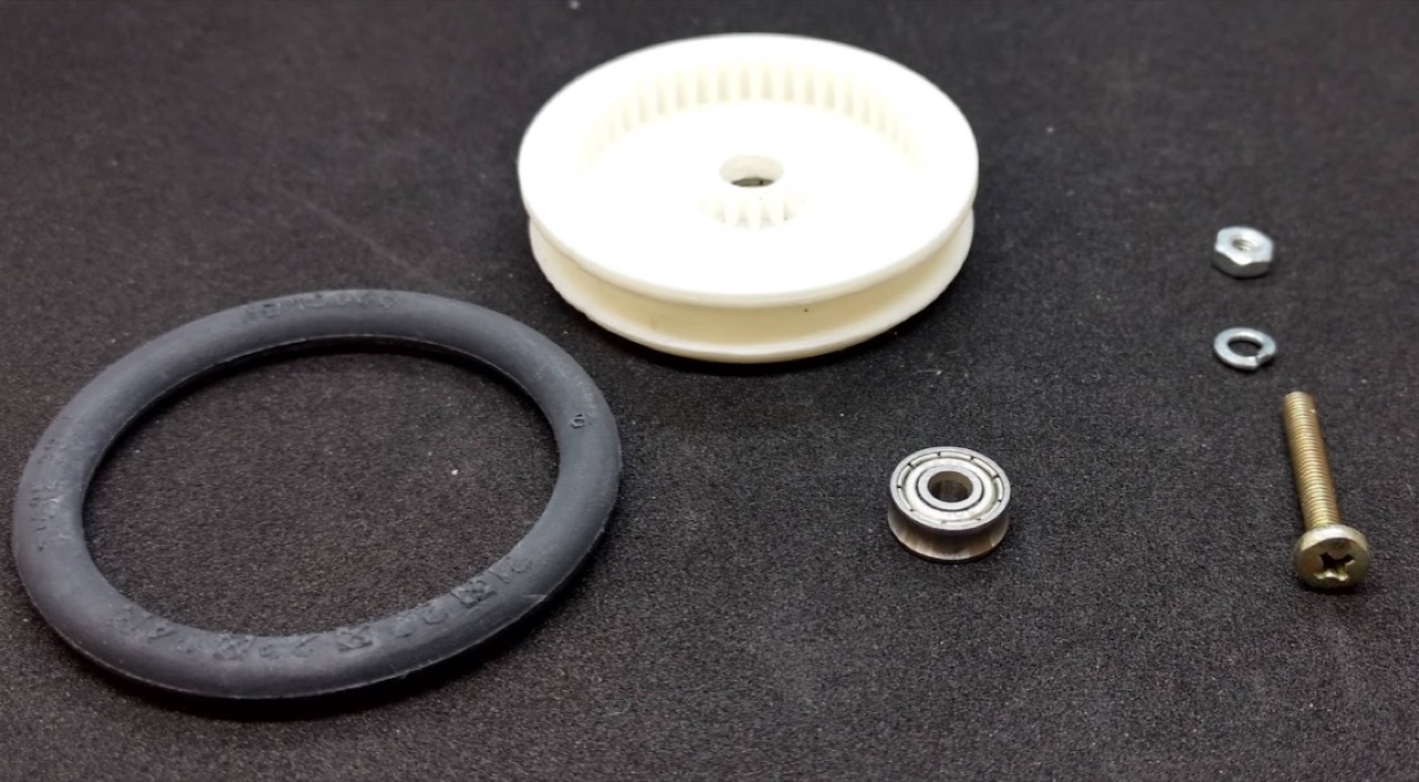
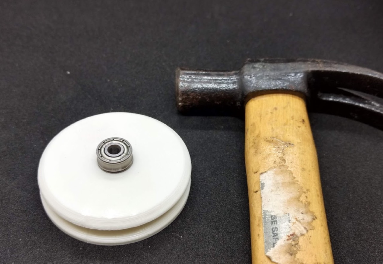
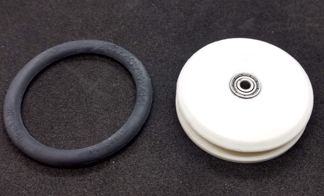
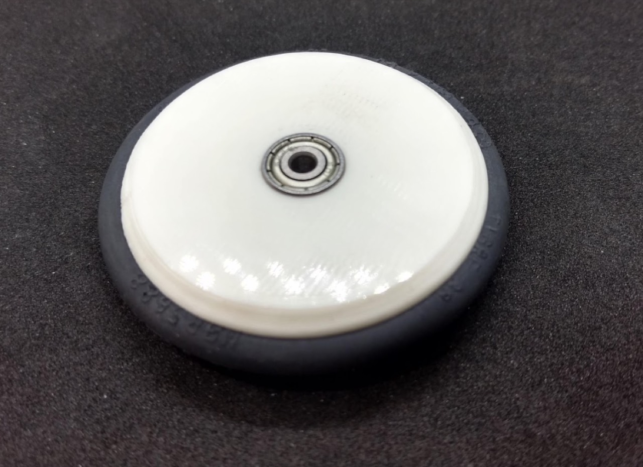
Install the wheel on the motor gear. The mesh should be smooth. A tiny drop of glue on the support screw into Chassis A keeps it from backing out.
Battery and Chassis B
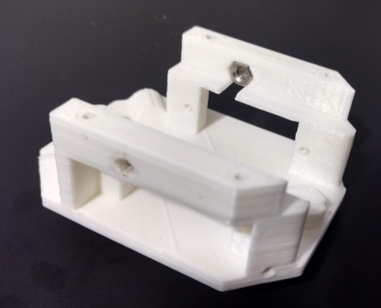
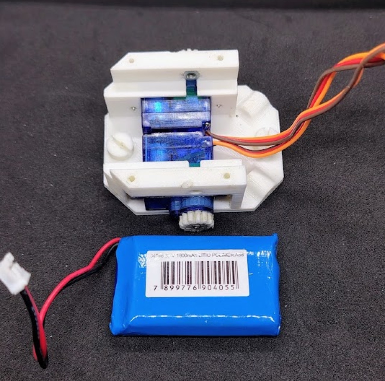
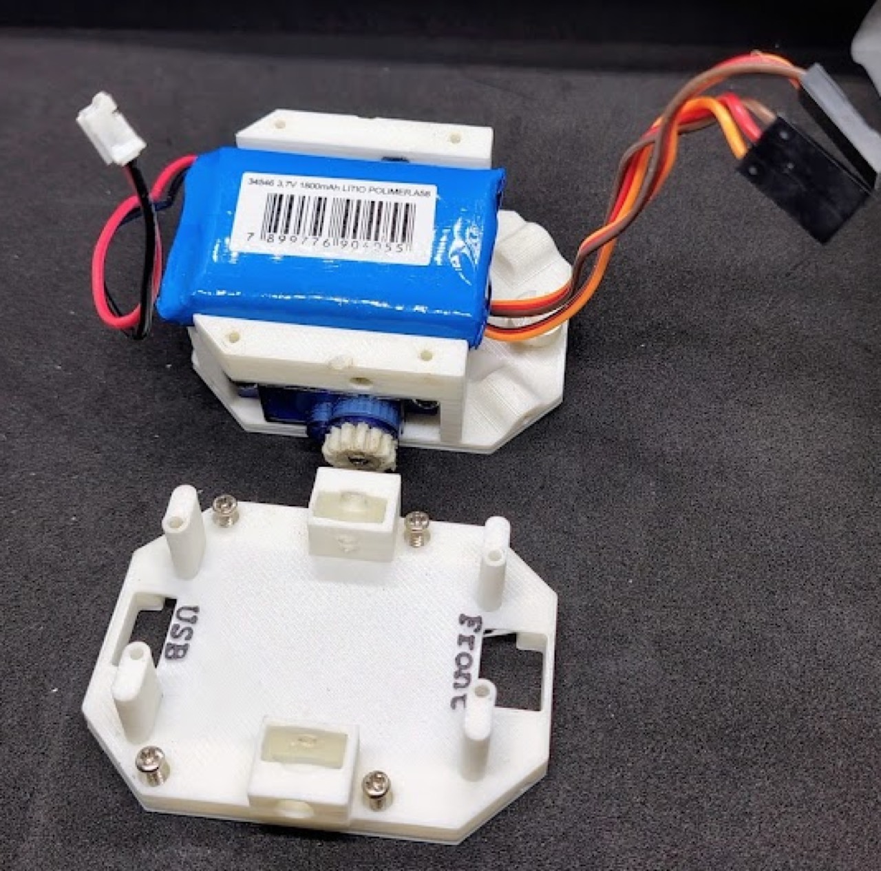
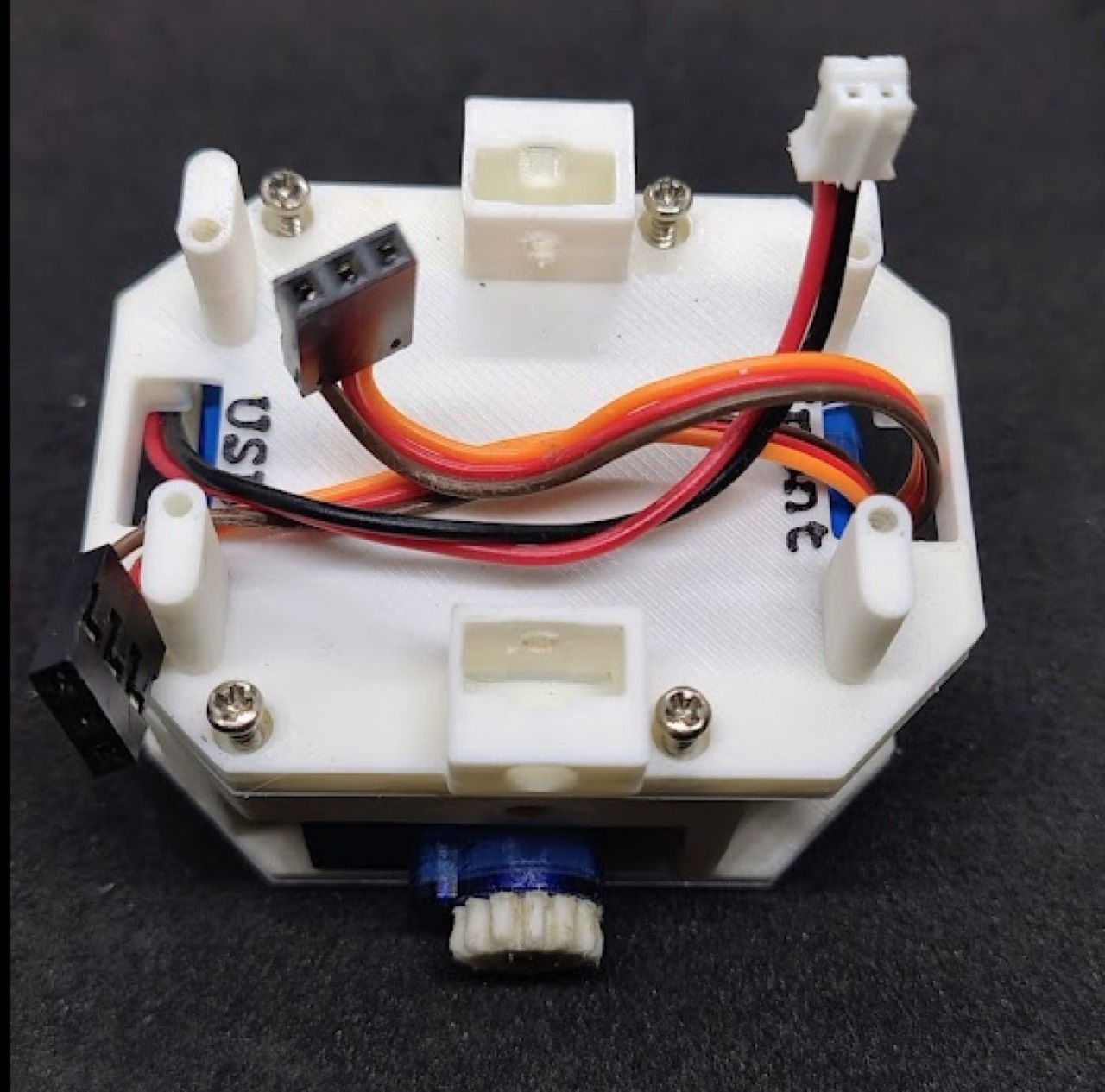
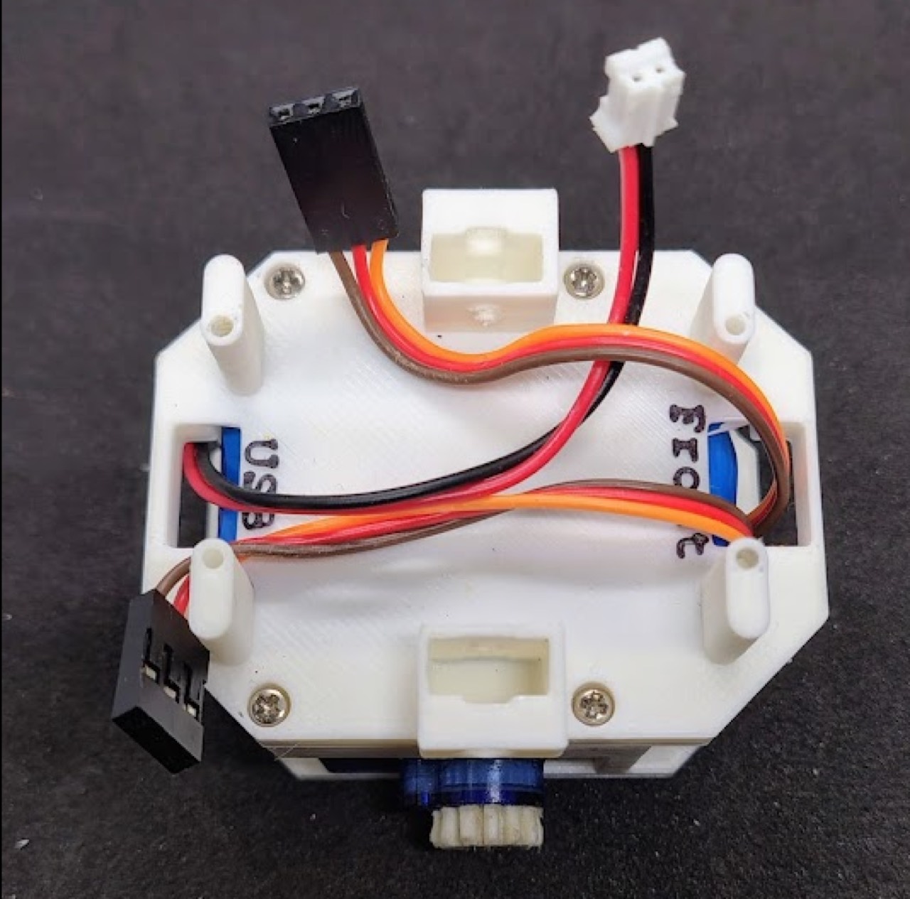
Seat the 1S Li-Po (paper: 3.7 V, 1800 mAh) in the cradle between A and B. Chassis B is labeled USB and Front: battery cable through USB, motor cables through Front.
Encoders
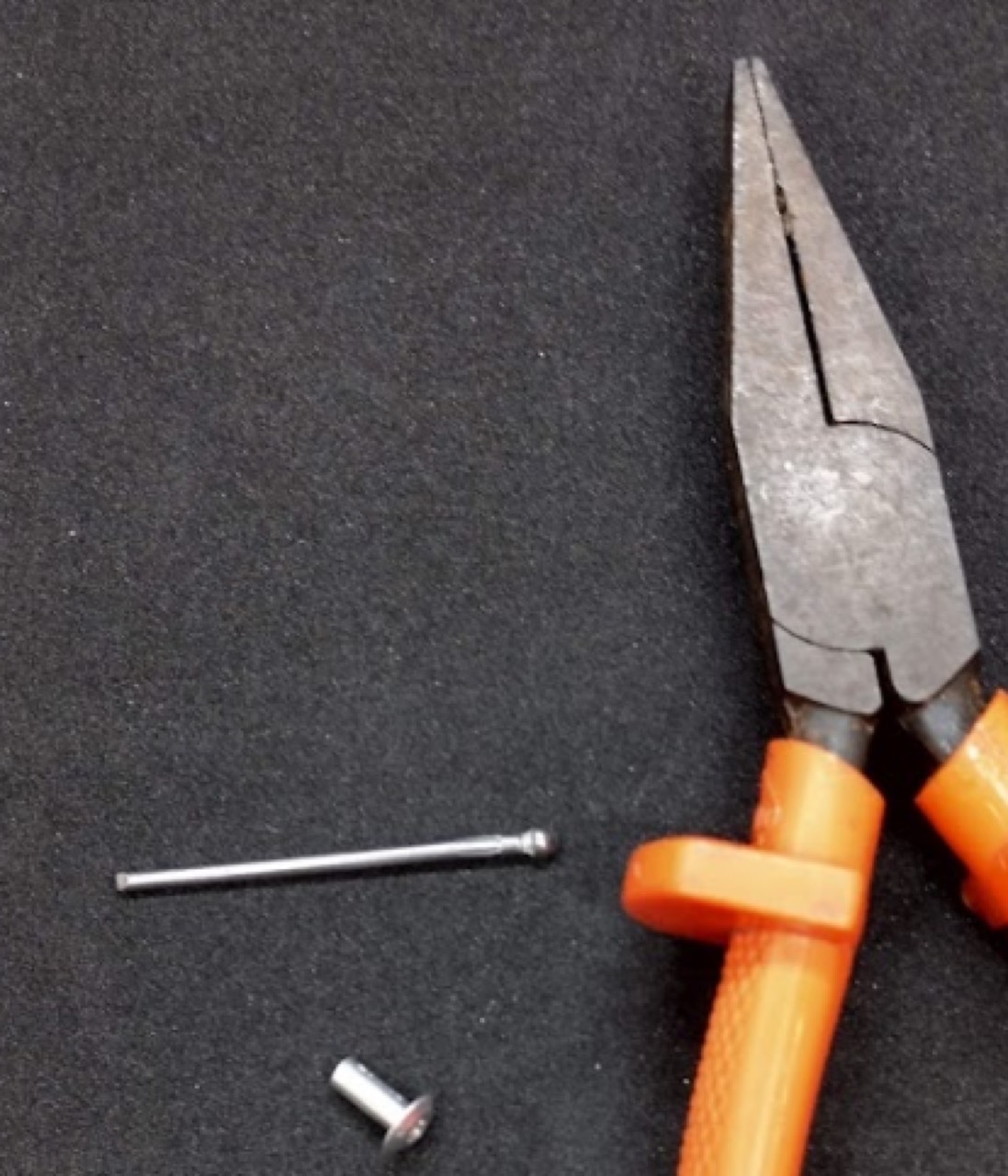
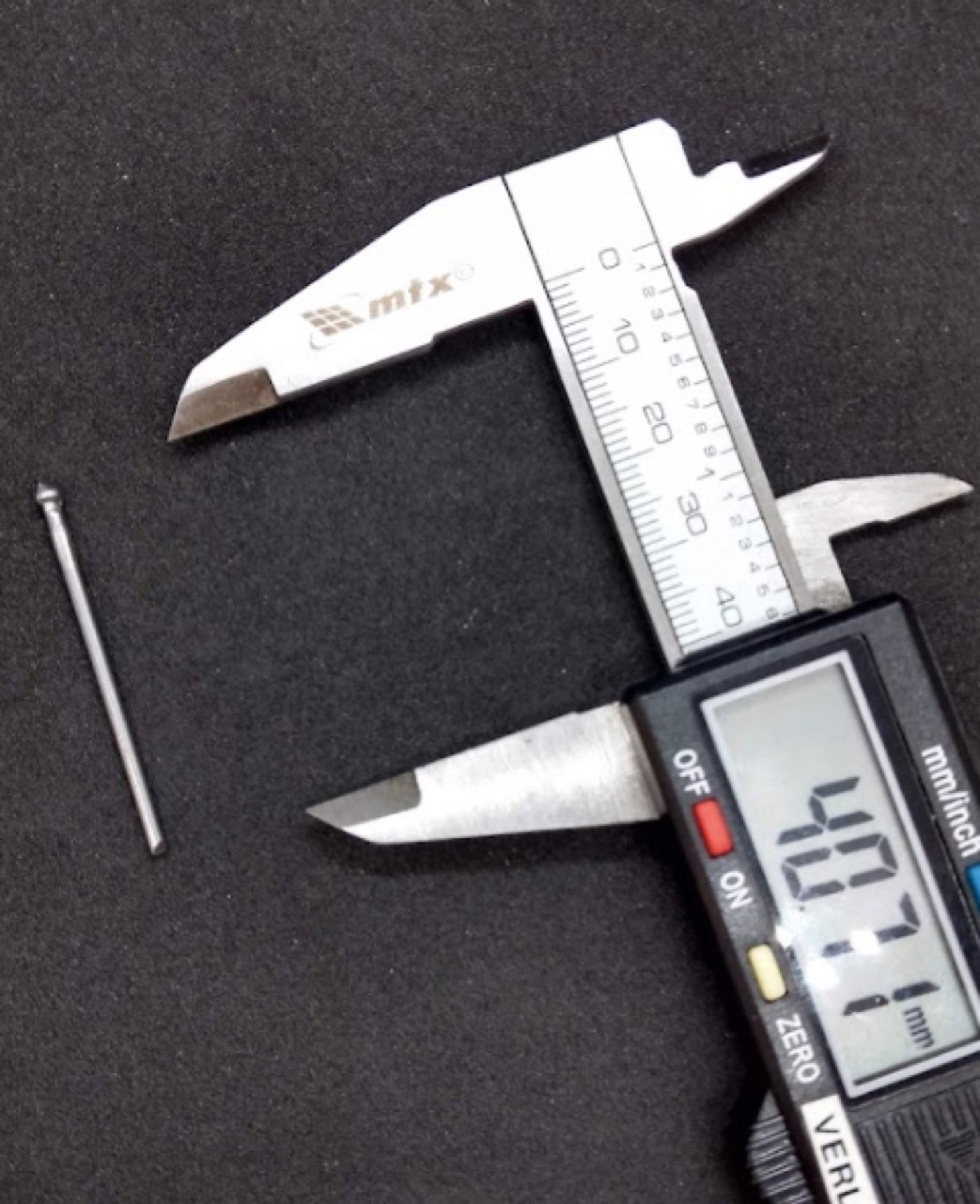
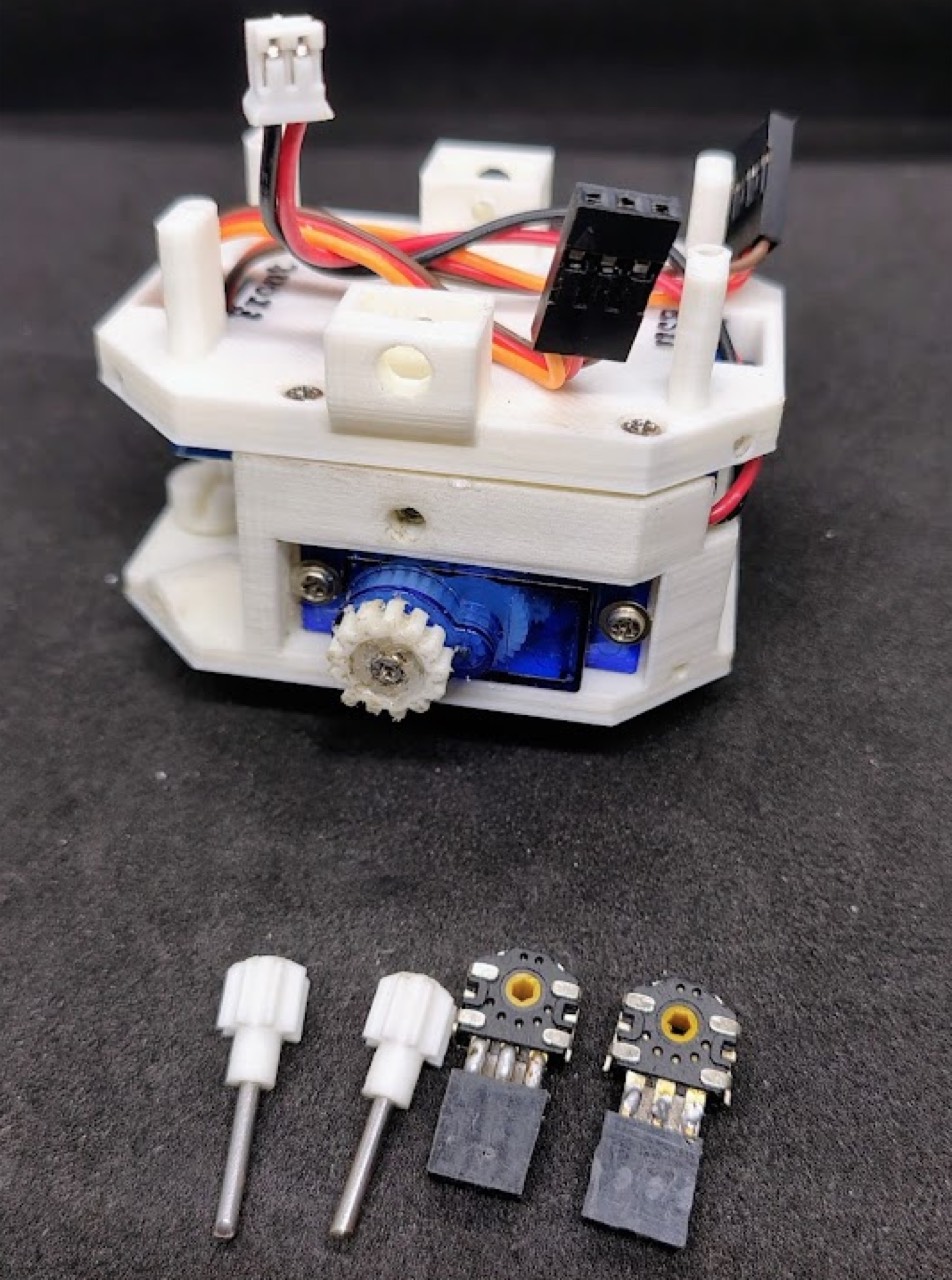
Mouse-style quadrature encoders. Remove the detent spring so the shaft is smooth. Solder a JST-PH header. Cut shafts to length; wear glasses.
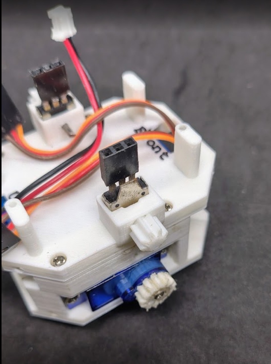
Board, cover, wiring
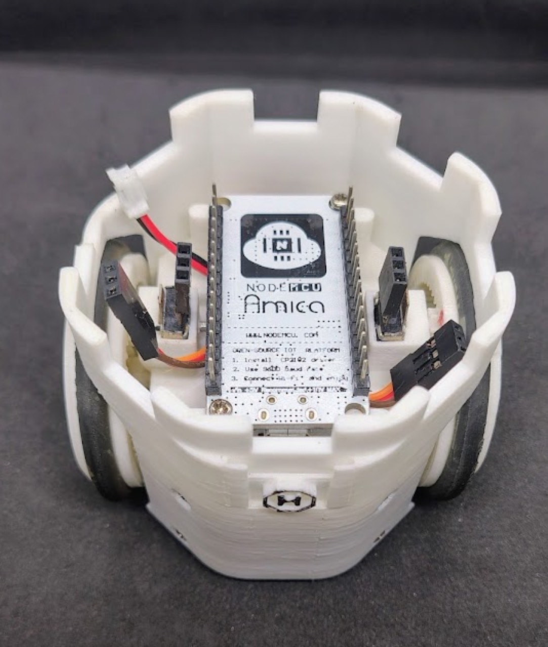
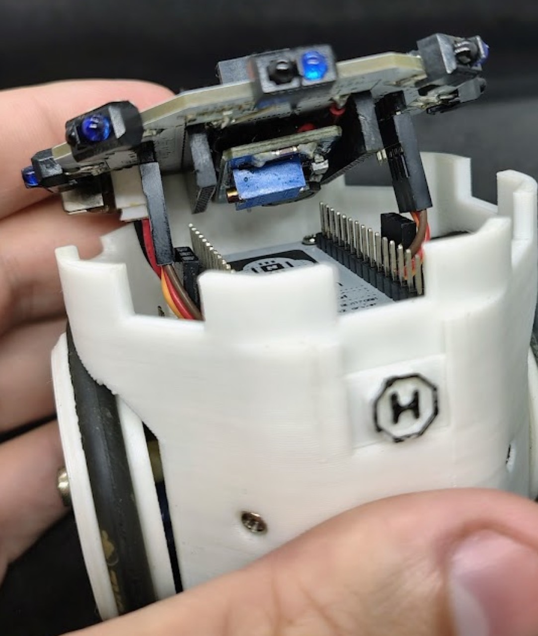
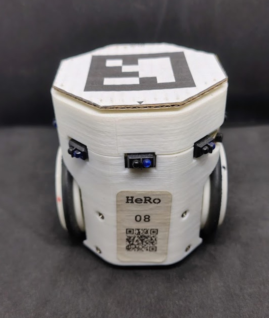
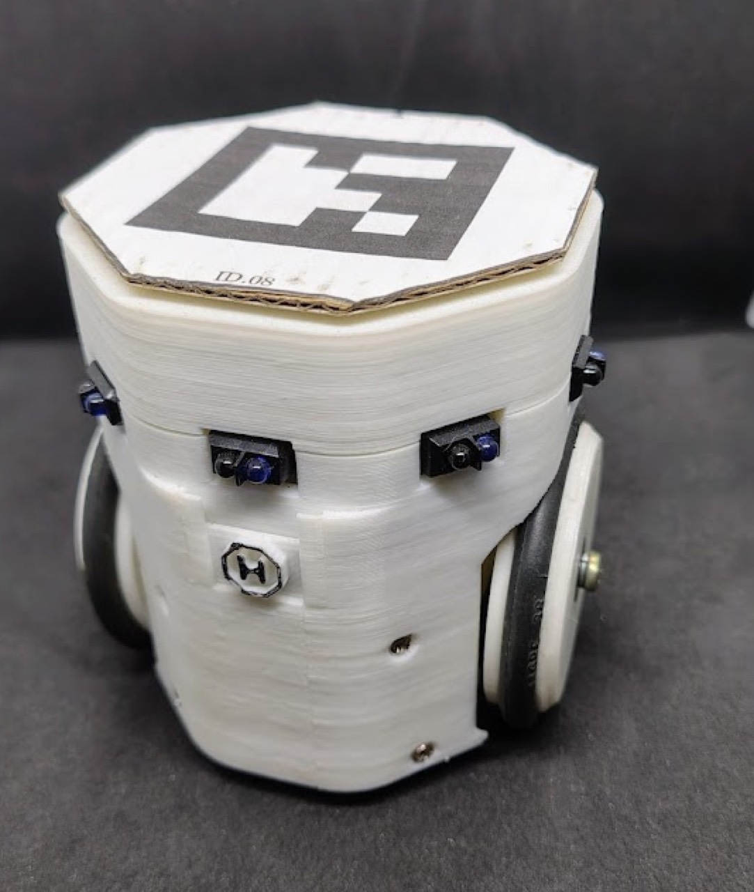
Mount the populated PCB on Chassis B. Fit the cover with eight screws — moderate torque. Then put the wheels on for the final motor → wheel → encoder check.
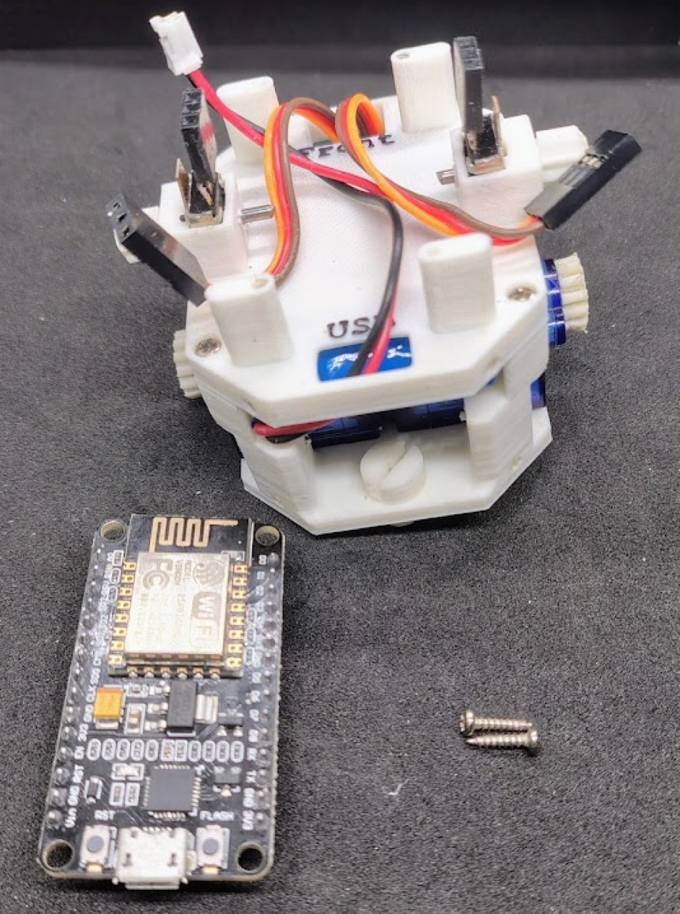
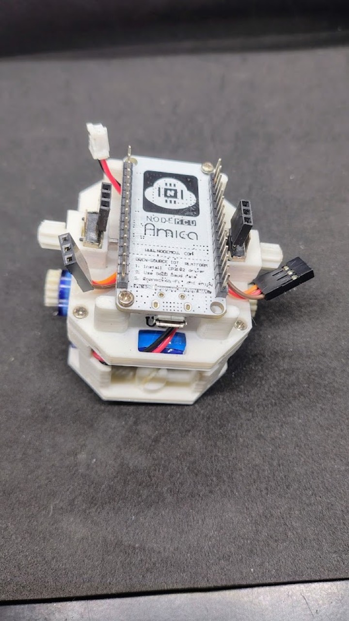
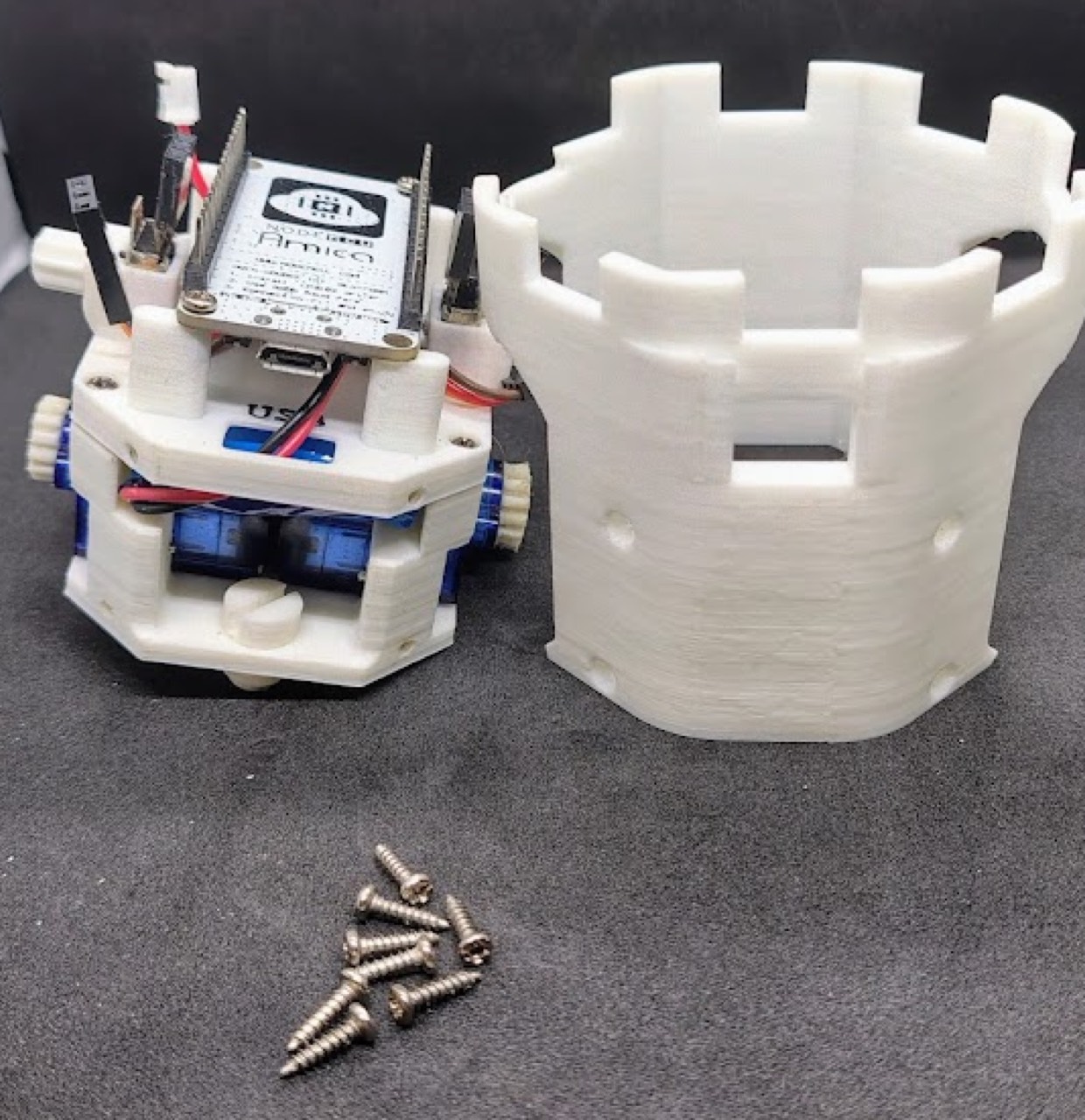
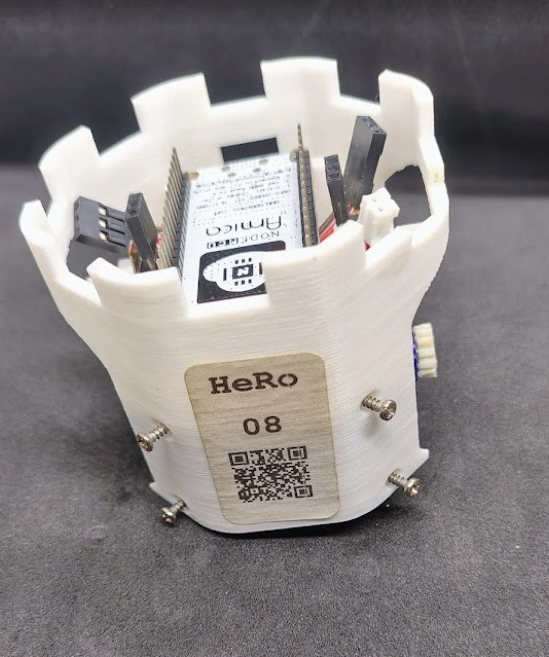
Servo leads: signal to PWM, red to 5 V, brown/black to GND. Battery JST last. Never reverse the pack.
E-hat
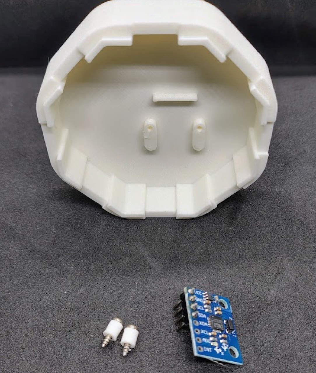
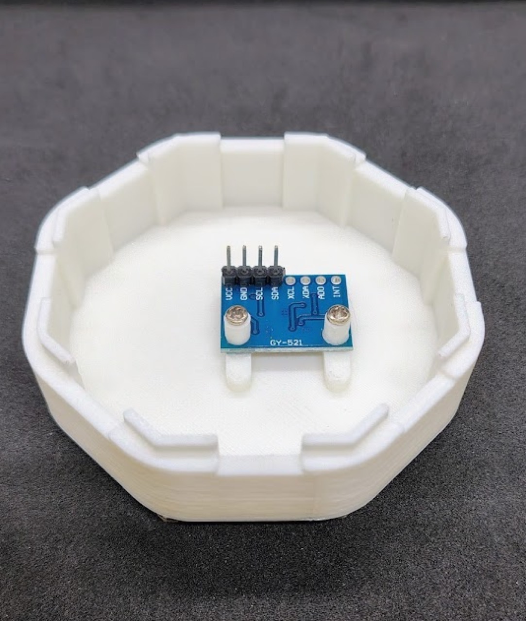
The paper’s e-hat is a 4-pin I²C/UART bus with 5 V at 800 mA. Solder male headers on the MPU6050, screw it into the printed hat, and plug the hat onto the I²C connector.
Troubleshooting
| Symptom | What the tutorial says to check |
|---|---|
| Motors dead or weak | PWM–5 V–GND order; boost still 5 V under load; pack > 3.6 V |
| Wheel wobble / backlash | Hub seating, bearings fully in, sand or shim the gear adapter |
| Encoder drops counts | Detent fully gone, JST joints, no lateral shaft play |
| IR silent | Sensor orientation, LED polarity, current-limit resistors |
| Board off | MT3608 at 5.0 V, JST polarity, switch solder |
| Boost hot | Stay ≤ 0.8 A continuous or add a heatsink |
Next: flash firmware, join ROS, then calibrate.