Build guide
Solder the board
SMD first, then through-hole. The tutorial times this at about 20 minutes of reading and 130 minutes of building. Figures are from the HeRo V2 Robot Build Tutorial (v1.0, 27 Sep 2025).
Passives · ICs · LEDs · Connectors · IR sensors · 5 V boost · Checks
Work current-limited (≤300 mA) until the smoke test. Treat the Li-Po as a live cell once it is connected.
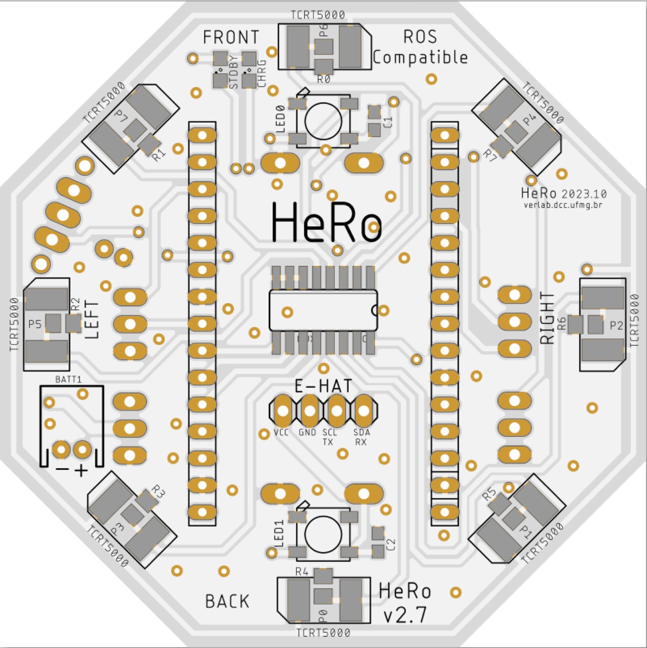
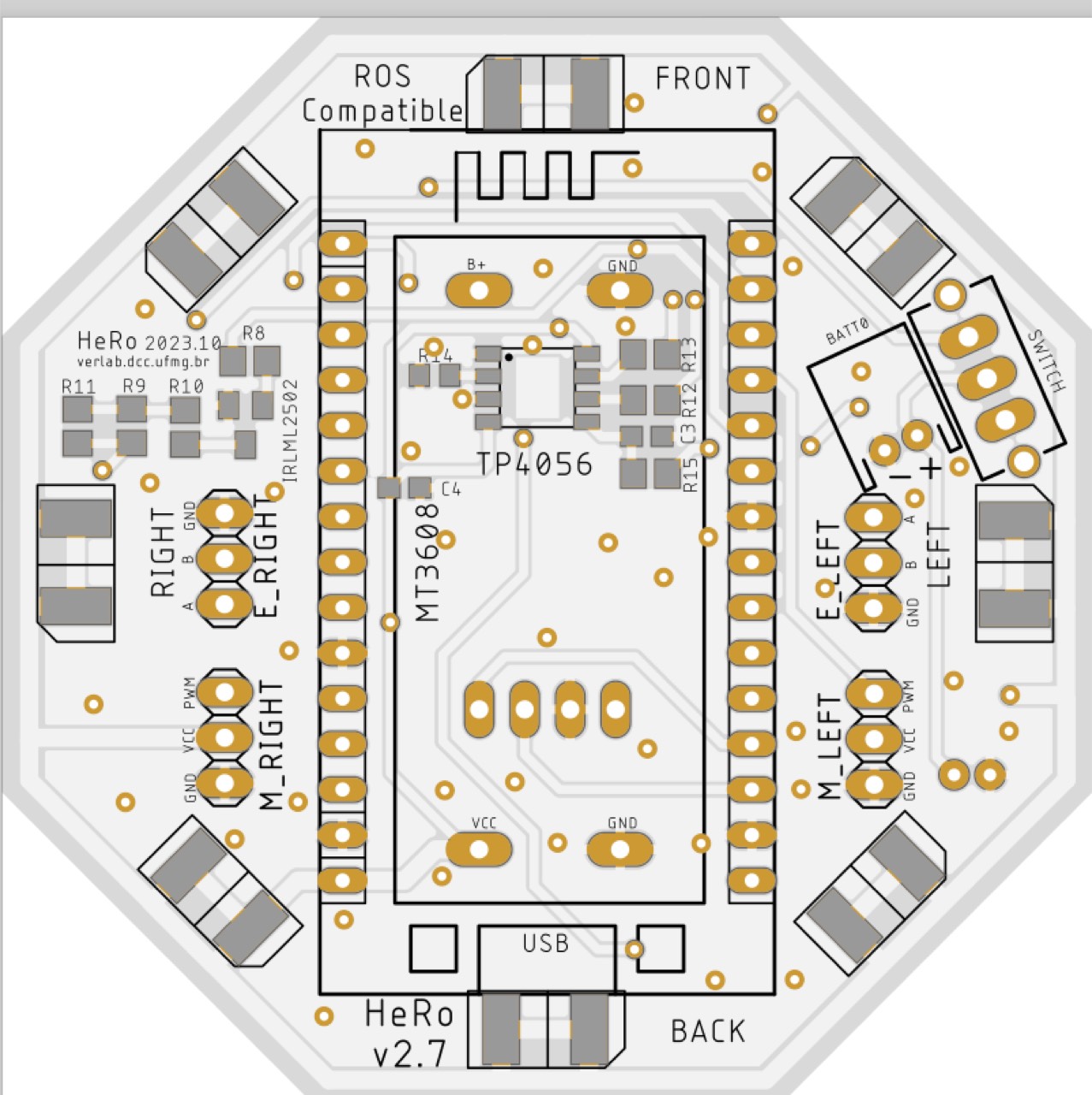
BOM on the board
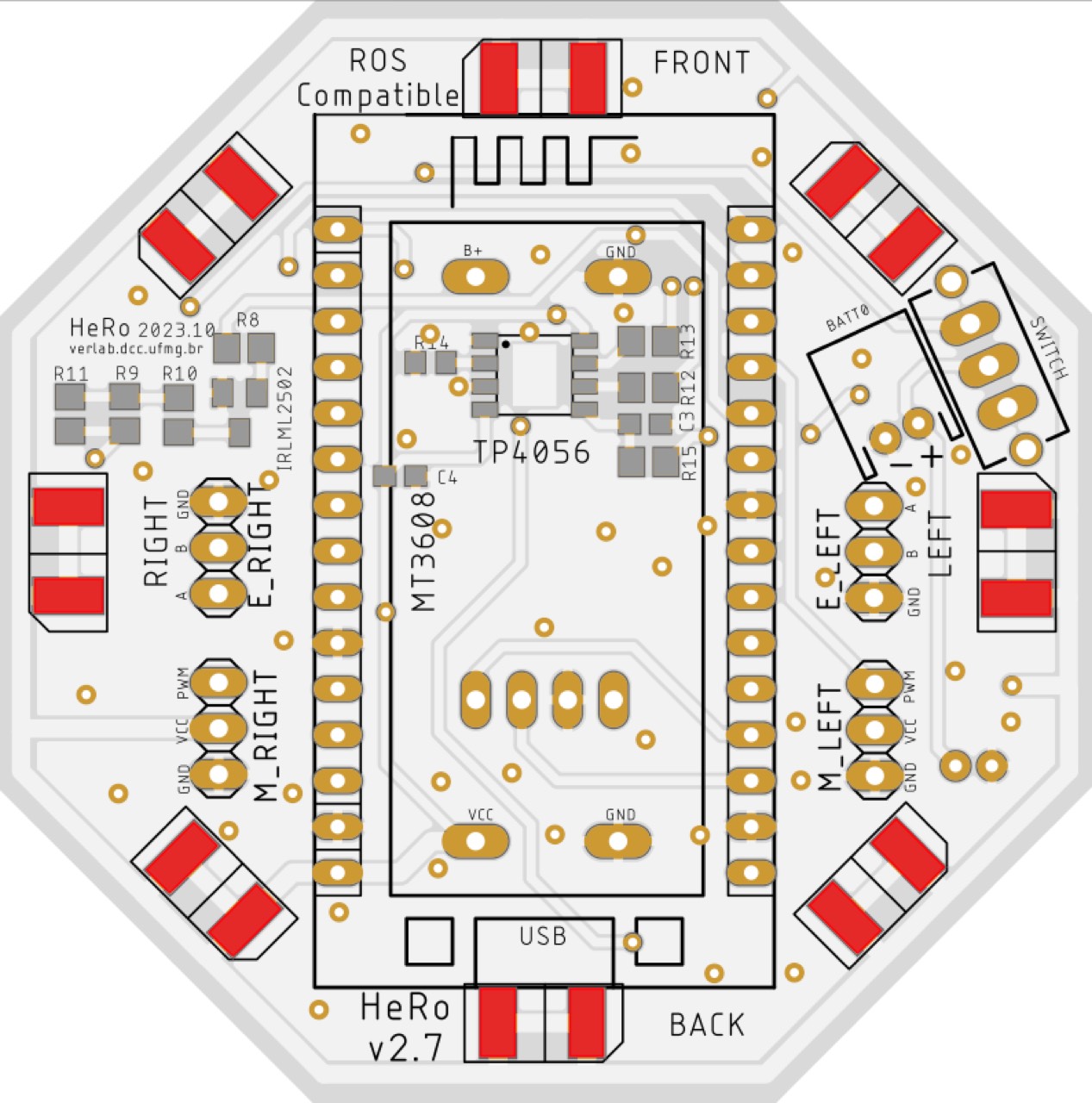
- Passives: R0–R8 (4k7), R9 (0 Ω), R10 (18 Ω), R15 (0 Ω), C1–C2 (100 pF). R11 is not mounted.
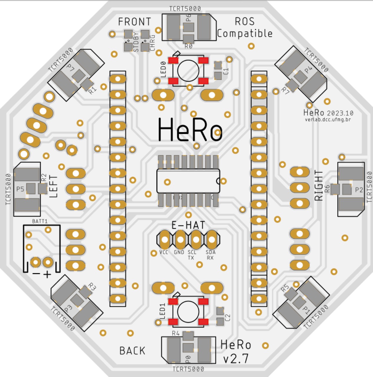
- Indicators: LED0–LED1 (WS2812B 5050). Optional charger LEDs: STDBY green 0805, CHRG red 0805.
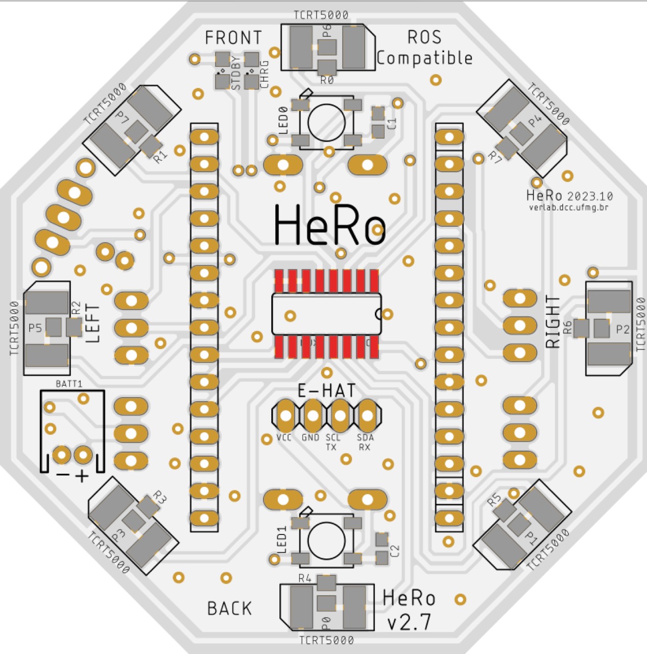
- ICs: IRLML2502 (SOT-23), CD4051 (SOIC-16), TP4056 (SOP-8, optional charger).
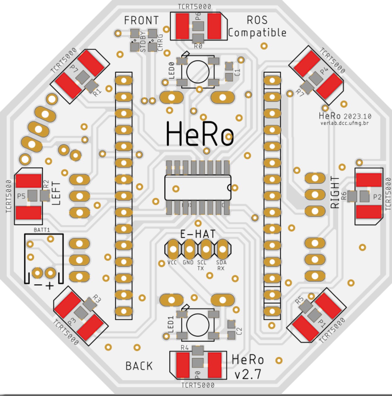
- Sensors: TCRT5000L ×8.
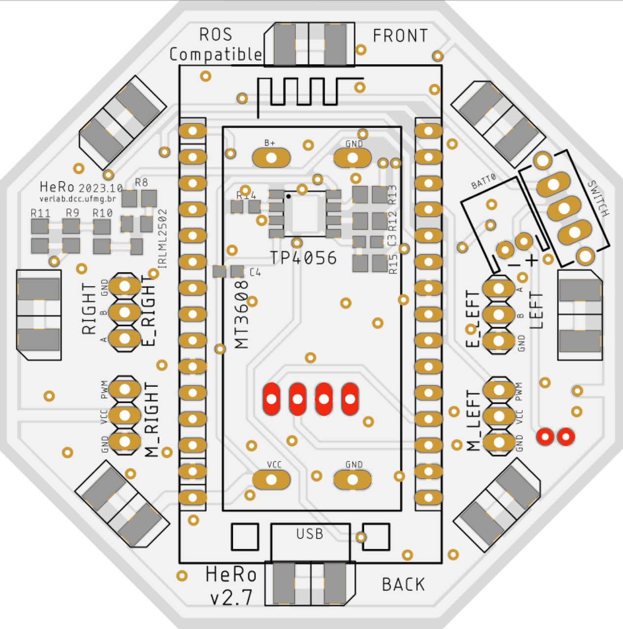
- Connectors: two JST-PH-2, 1×4 female (I²C/UART), four 1×3 male (E/M), two 1×16 female (ESP), slide switch.
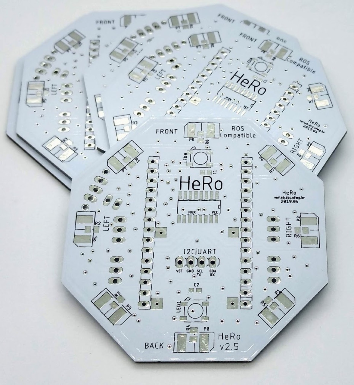
Soldering order (SMD → THT)
1. Small passives — C0603 then R0805 (C1–C2; C3–C4 optional; R0–R10, R12–R15). Leave R11 empty.
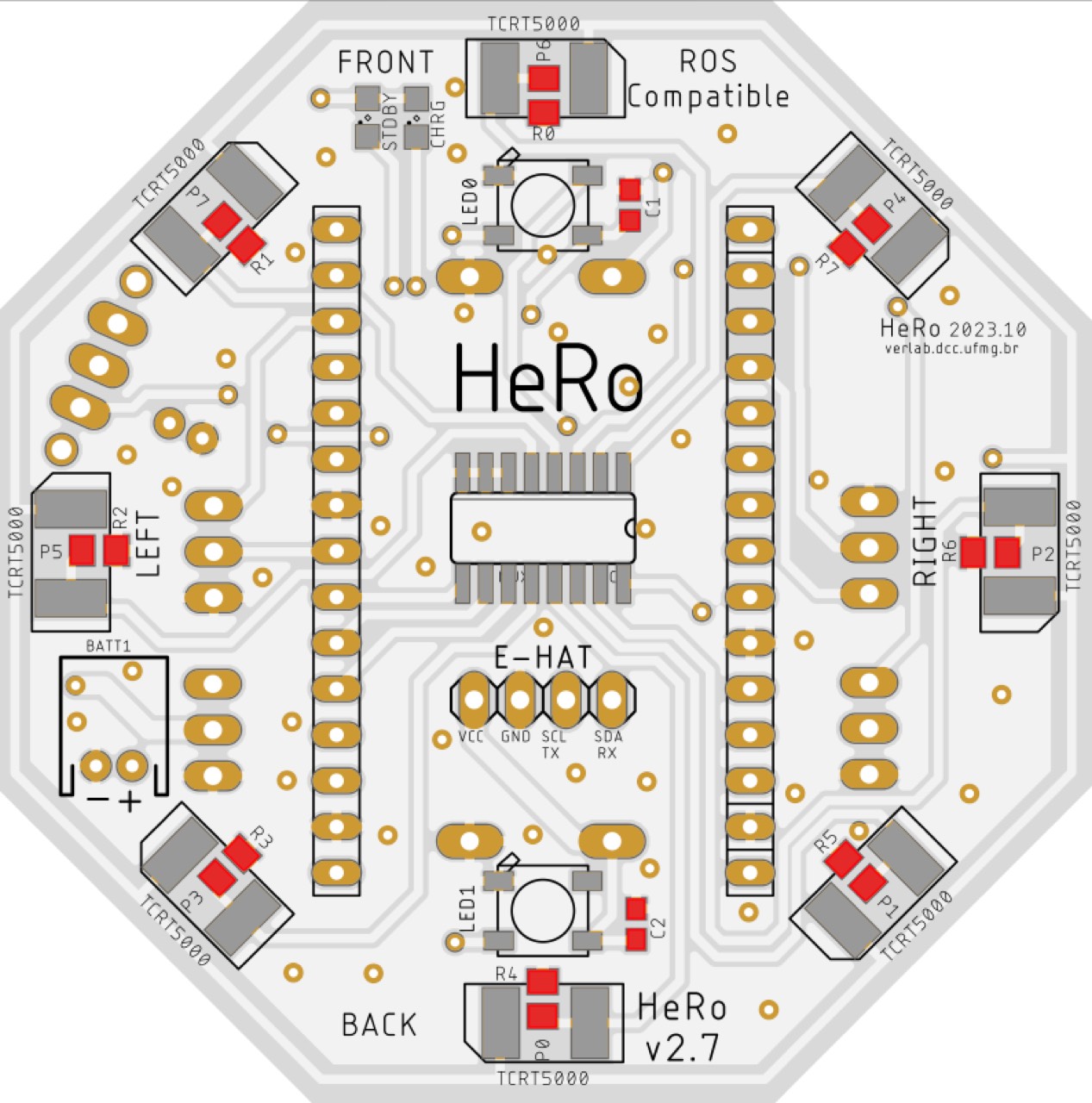
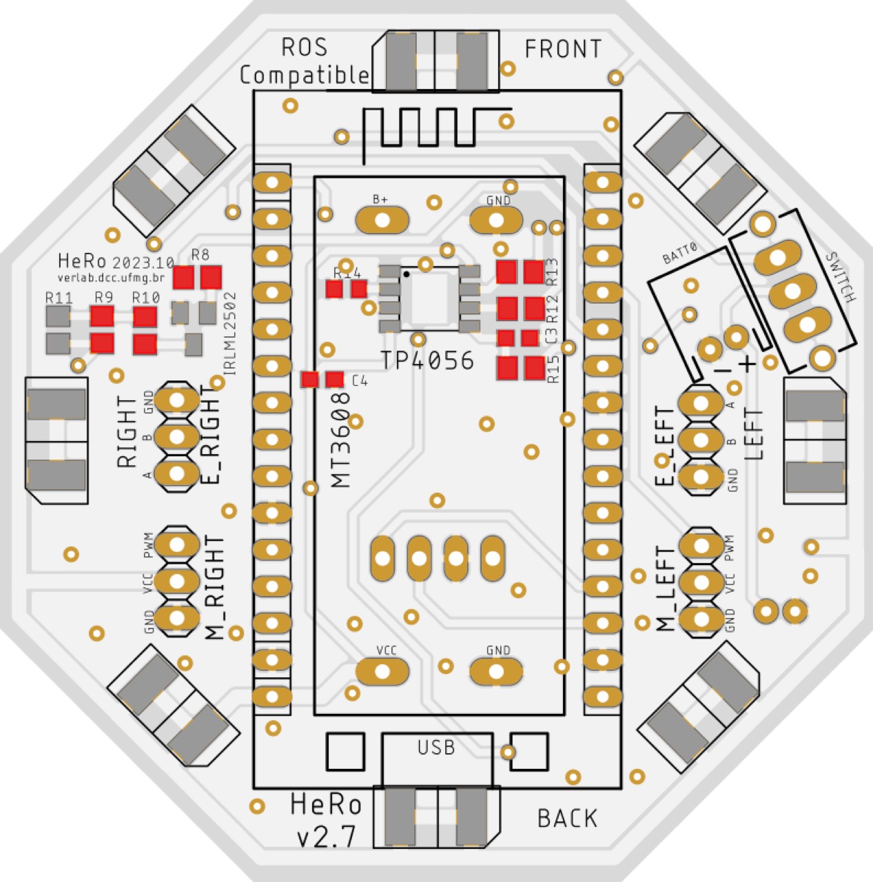
2. ICs — TP4056 if you want onboard charge, then CD4051, then IRLML2502. Pin-1 / orientation dot to the silkscreen. Inspect bridges.
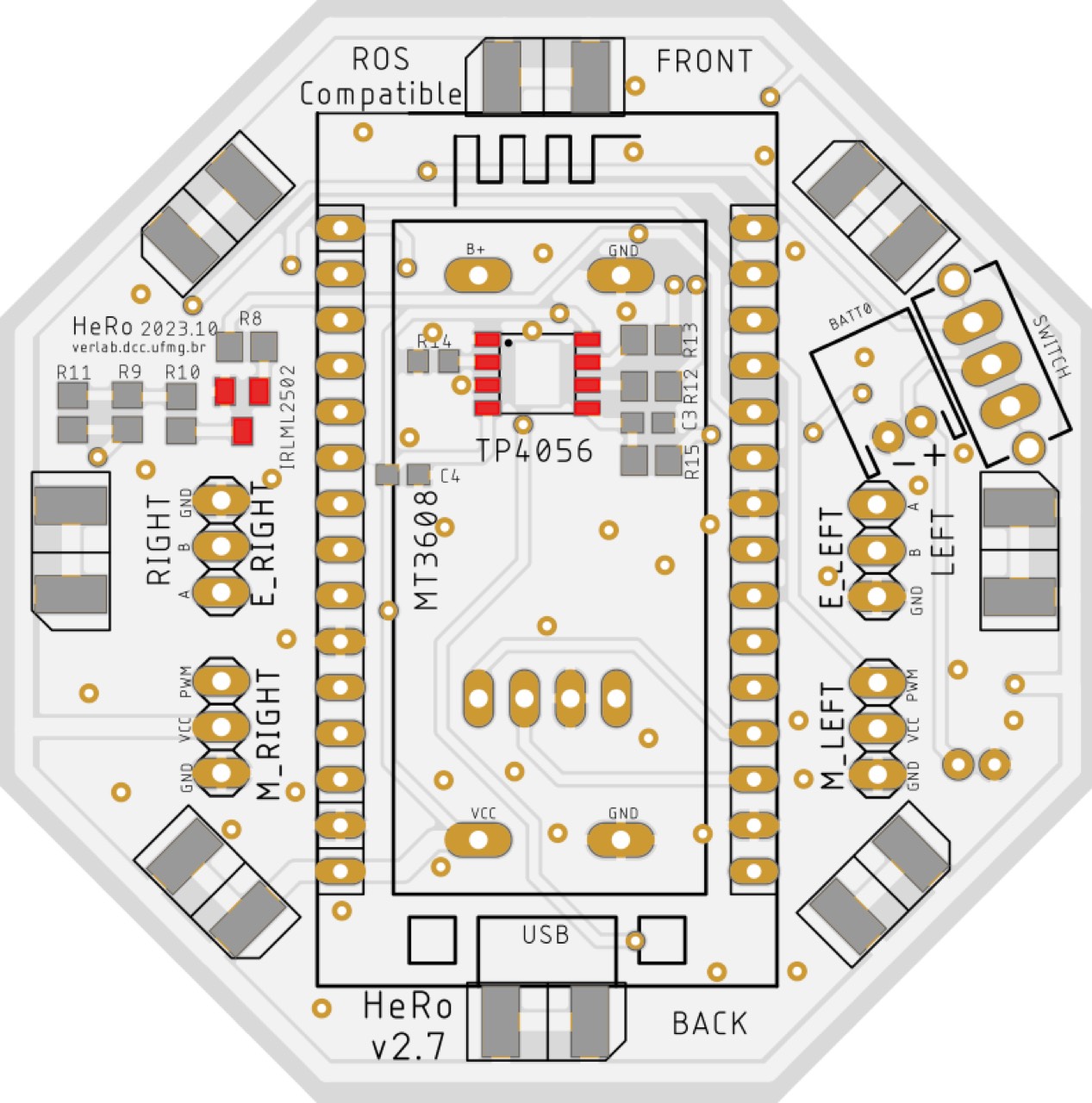
3. Addressable LEDs — WS2812B, arrow DIN → DOUT, polarity to silk. Continuity-check the pads.
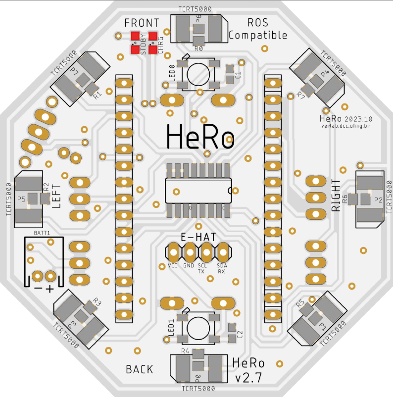
4. Connectors and switch — JST-PH-2 ×2, I²C/UART header, encoder/motor headers, ESP sockets, slide switch.
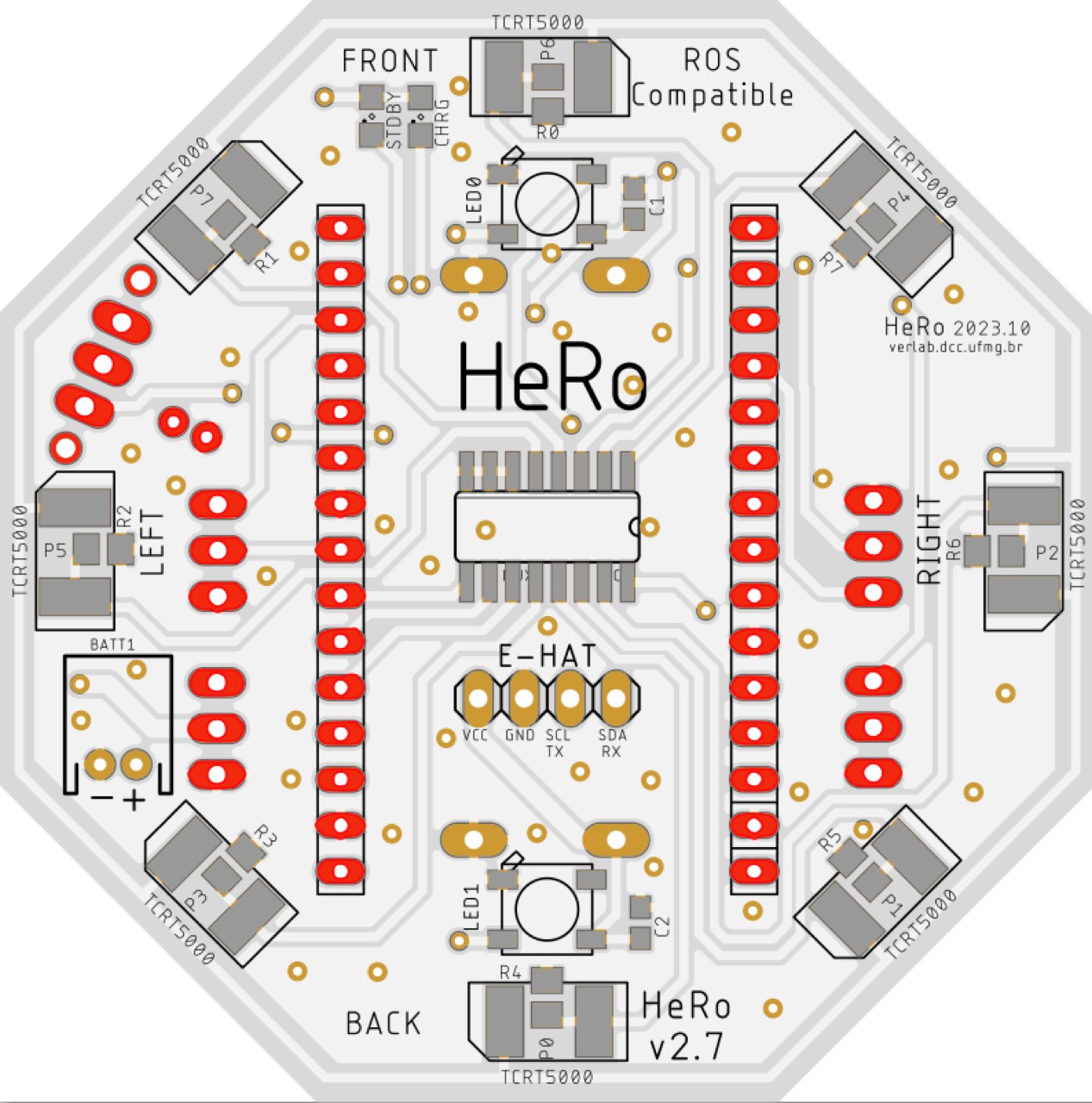
5. IR sensors — eight TCRT5000L, same standoff, coplanar, gap aligned around the ring.
Tune the MT3608 to 5.0 V
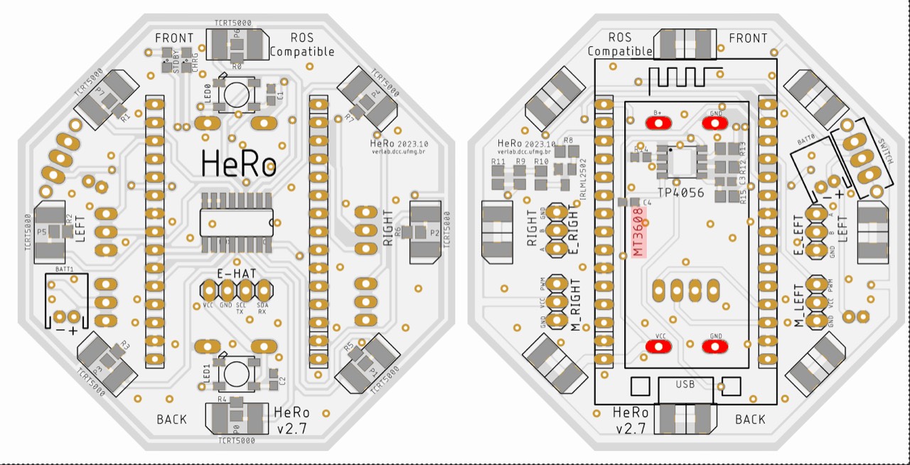
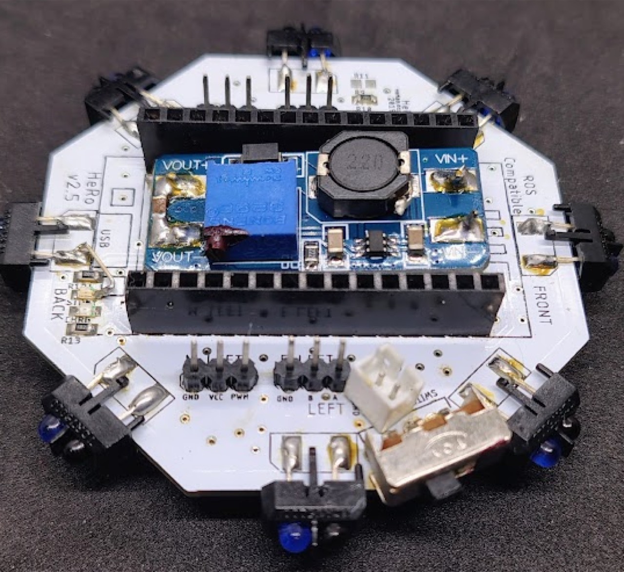
The paper uses an MT3608 step-up so the 3.7 V pack becomes a 5 V rail (motors included).
- PSU + → VIN+, PSU GND → VIN−. Meter on VOUT+/VOUT−.
- Set the bench supply to 4.0 V, current limit 0.30 A.
- Turn the trimpot slowly toward 5.00 V. Do not overshoot.
- Recheck under a short dummy load: 100 Ω (~50 mA), then 6.2 Ω (~0.8 A) or 5 Ω (~1.0 A) in bursts.
- Power off. Mark the module “5 V”.
Electrical checks
Unpowered: GND continuity; 0 Ω jumpers R9/R15; no 5 V↔GND or 3V3↔GND shorts.
Powered (bench or battery): 5.0 V / 0.3 A limit, switch on, watch quiescent current. Nothing should run hot.
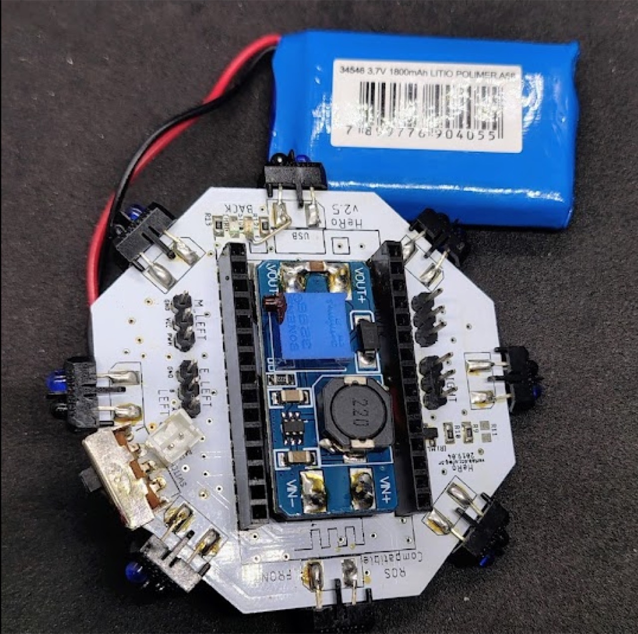
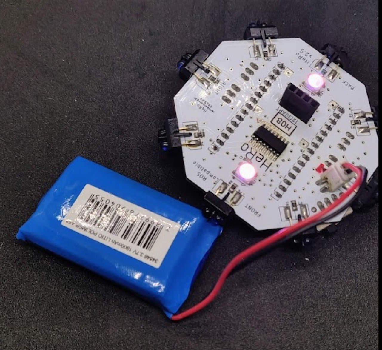
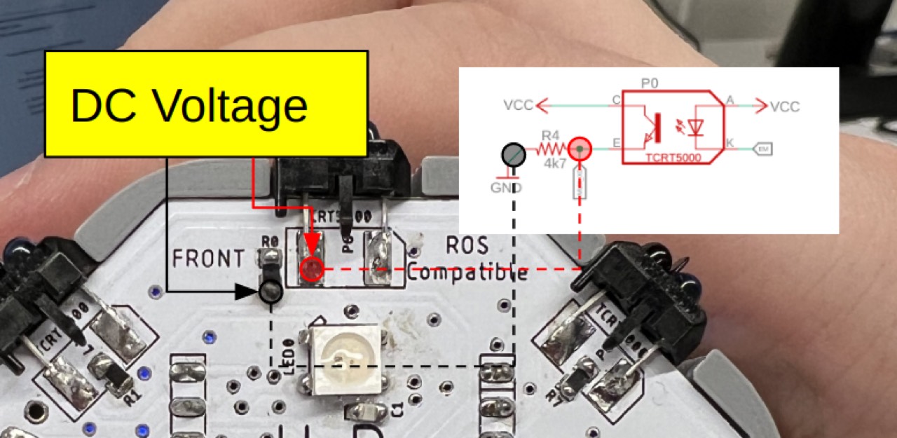
Drive the WS2812B with a blink or rainbow. Confirm I²C pull-ups (~4.7 kΩ to 3V3) and an MPU6050 ACK if the e-hat is fitted. Walk the CD4051 channels; IR voltages should move with a white/black card.
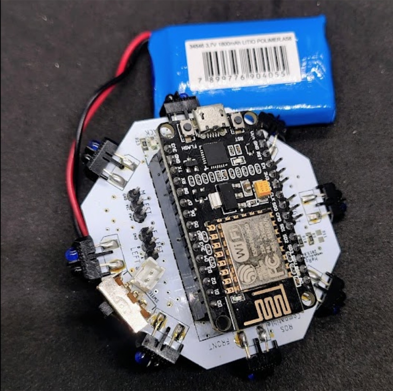
Optional smoke test: flash the stock firmware over USB (battery disconnected) and watch the serial boot at 115200.